


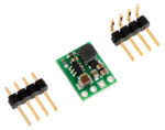


5V Step-down Voltage Regulator
These step-down voltage regulators generate lower output voltages from input voltages as high as 42V. They are switching regulators (also called switched-mode power supplies (SMPS) or DC-to-DC converters) and have a typical efficiency between 80% to 90%, which is much more efficient than linear voltage regulators, especially when the difference between the input and output voltage is large.
The regulator has short-circuit protection, and thermal shutdown prevents damage from overheating. The board does not have reverse-voltage protection.
Features:
- Input voltage: [output voltage + dropout voltage] to 42V.
- Fixed 5V output with 4% accuracy.
- Maximum output current: 300mA.
- 1.25 MHz switching frequency.
- 2mA typical no-load quiescent current (20μA typical quiescent current with SHDN = LOW).
- Integrated over-temperature and over-current shutoff.
- Small size: 13mm × 10mm × 3mm.
Contents:
- 1 x 5V Step-down Voltage Regulator.
- 1 x 4 pin headers of 2.54mm pitch – Straight.
- 1 x 4 pin headers of 2.54mm pitch – right angled.
In Use:
- The regulator has four connections: shutdown (SHDN), input voltage (VIN), ground (GND), and output voltage (VOUT).
- The SHDN pin can be driven low (under 0.3V) to turn off the output and put the board into a low-power state that typically draws 20μA, and it can be driven high (above 2.3V) to enable the board. If you do not need to use the shutdown feature, the SHDN pin can be directly connected to VIN to permanently enable the board. You should not leave this pin disconnected as this can result in unpredictable behavior.
- The input voltage, VIN, should exceed VOUT by at least the regulator’s dropout voltage (see below for graphs of dropout voltages as a function of the load), and you must ensure that noise on your input does not exceed the 42V maximum. Additionally, please be wary of destructive LC spikes (see below for more information).
- The output voltage, VOUT, is fixed at 5V.
- The four connections are labeled on the back side of the PCB, and they are arranged with a 2.54mm spacing along the edge of the board for compatibility with solderless breadboards, connectors, and other prototyping arrangements that use a 2.54mm grid. You can solder wires directly to the board or solder in either the 4×1 straight male header strip or the 4×1 right-angle male header strip that is included.
Dimensions:
- PCB Length: 13mm.
- PCB Width: 10mm.
- PCB Height: 3mm.
Requires:
- Soldering Iron.
- Solder.
Pololu Stock Code:
- 2098